Basics on "Electrical Instruments and Measurements" for Electrical Engineers is an essential requirements of Mechanical Engineers as most of the times they will have to involve Engineers Meeting at management level about the progress and status of the plant. Generally, mechanical engineers may not be familiar with electrical field, but as a plant engineer he should have basic knowledge of the instruments which they are using including motors, generators and bus-bar systems. Many a times plant engineers fails to express their views about other tools or equipment and unable convenience the working progress of the equipment or tools to the management or seniors. Hence, as per my experience, one should know basics existing products of his related field so as to control the plant situation.
As already you may be aware that these are divided into (1) absolute instruments and (2) secondary instruments. Absolute instruments are those which give the value of the quantity to be measured in terms of the constants of the instrument and their deflection only. No previous calibration or comparison is necessary in their case. The example of such an instrument is tangent galvanometer which gives the value of current in terms of the tangent of deflection produced by the current, the radius and number of turns of wire used and the horizontal component of earth’s field.
Secondary Instruments are those in which the value of electrical quantity to be measured can be determined from the deflection of the instruments only when they have been pre calibrated by comparison with absolute instruments. Without calibration, the deflection of such instrument is meaningless.
It is the secondary instruments which are most generally used in everyday work, the use of the absolute instruments being merely confined within lab as standardizing instruments.
ELECTRICAL PRINCIPLES OF OPERATION
All electrical measuring instruments depend for their action on one of the many physical effects of an electric current or potential and generally classified according to which of these effects is utilized in their operation. The effects generally utilized are:-
Magnetic Effect- for ammeters and voltmeters usually.
Electrodynamic effect- for ammeters, voltmeters and wattmeter usually.
Electromagnetic effect- for ammeters, voltmeters, wattmeter’s and watt hour meters.
Thermal effect- for ammeters and voltmeters.
Chemical effect- for d.c. ampere hour meters.
Electrostatic effect- for voltmeters only.
Another way to classify the secondary instrument is to divide them into (1) indicating instruments, (2) recording instruments and (3) integrating instruments.
Indicating instruments are those which indicate the instantaneous value of the electrical quantity being measured at the time at which it is being measured. Their indications are given by pointers moving over calibrated dials. Ordinary ammeters, voltmeters and wattmeter belong to this class.
Recording instruments are those which instead of indicating by means of a pointer and a scale the instantaneous value of an electrical quantity, give a continuous record of the variations of such a quantity over a selected period of time. The moving system of the instrument carries an inked pen which rests lightly on a chart or graph that is moved at a uniform and low speed, in a direction perpendicular to that of the deflection of the pen. The path traces out by the pen presents a continuous record of the variations in the deflection of the instruments.
Integrating instruments are those which measure and register by a set of dials and pointers either the total quantity of the electricity (in amp-hours) or the total amount of electrical energy (in watt hours or Kwh.) supplied to a circuit in a given time. Their summation gives the product of time and the electrical quantity but gives no direct indication as to the rate t which the quantity or energy is being supplied because their registrations are independent of this rate provided the current flowing through the instruments is sufficient to operate it.
Ampere hour and watt hour meters are fall in this class.
ESSENTIALS OF INDICATING INSTRUMENTS
Indicating instruments are those which indicate the value of quantity that is being measured at the time at which it is measured. Such instruments consist essentially of a pointer which moves over a calibrated scale and which is attached to a moving system pivoted in jeweled bearings. The moving system is subjected to the following three torques:
1. A deflecting (or operating) torque.
2. A controlling (or restoring) torque.
3. A damping torque.
DEFLECTING TORQUE
The deflecting or operating torque (Td) is produced by utilizing one or other effects mentioned in figure 1. i.e. magnetic, electrostatic, electrodynamics’, thermal or inductive etc. The actual method of torque production depends on the type of instrument and as you can see in next page. The deflecting torques causes the moving system (and hence the pointer attached to it.) to move from its zero position i.e. its position when the instrument is disconnected from the supply.
CONTROLLING TORQUE
The deflection of the moving system would be indefinite if there were no controlling or restoring torque. This torque opposes the deflecting torque and increases with the deflection of the moving system. The pointer is brought to rest at a position where the two opposing torques are equal. The deflecting torques ensures that currents of different magnitudes shall produce deflections of the moving systems in proportion to their size. Without such a torque, the pointer would swing over to the maximum deflected position irrespective of the magnitude of the current to be measured. Moreover, in the absence of restoring torque, the pointer once deflected, would not returns to its zero position on removing the current. The controlling, restoring or balancing torque in indicating instruments is either obtained by a spring or by gravity as explained below.
SPRING CONTROL
A hair spring, usually of phosphor bronze, is attached to the moving system of the instruments as shown in figure. With the deflection of the pointer, the spring is twisted in the opposite direction. This twist in the spring producing restoring torque which is directly proportional to the angle of the deflection of the moving system. The pointer comes to a position of rest (or equilibrium) when the deflecting torque (Td) and controlling torque (TC) are equal. For example, in permanent magnet moving coil type of instruments, the deflecting torque is proportional to the current passing through them.
Therefore, TD is proportional to I,
And for spring control, TC is proportional to theta,
As TC = Td, Theta is proportional to Current I.


Since deflection theta is directly proportional to current I, the spring controlled instruments have a uniform or equally spaced scales over the whole of their range as shown in figure.
To ensure that controlling torque is proportional to the angle of deflection, the spring control should have a fairly large numbers of turns so that angular deformation per unit length, on full scale deflection, is small. Moreover, the stress in the spring should be restricted to such a value that it does not produce a permanent set in it.
Springs are made of such material which are non-magnetic, are not subject to much fatigue, have low specific resistance-especially in cases where they are used for leading current in or out of the instrument and have low temperature co efficient.
GRAVITY CONTROL
Gravity control is obtained by attaching a small adjustable weight to some part of the moving system, such that the two exert torques in the opposite directions. It can be seen in figure that the controlling torque or restoring torque is proportional to the sine of the angle of deflection,
I.e. TC is proportional to sine theta. The degree of control is adjusted by screwing the weight up or down the carrying system.
If Td is proportional to current I,
The position of rest,
Td=TC OR Current is proportional to sine theta. It will be seen from the figure that, as
Theta approaches 900, the distance AB increases by a relatively a small amount for a given change in the angle than when theta is just increasing from its zero value. Hence, gravity controlled instruments have scales which are not uniform but are cramped or crowded at their lower ends as shown in figure.
As compared to spring control, the disadvantage of gravity control is,
It gives cramped scale.
The instruments have to be kept vertical.
However, gravity control has the following advantages:
It is cheap.
It is unaffected by temperature.
It is not subject to fatigue or deterioration with time.
DAMPING TORQUE
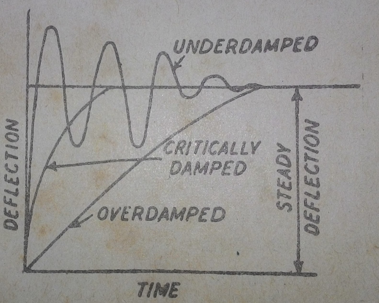
A damping force is one which acts on the moving system of the instruments only when it is moving and always opposes its motion. Such stabilizing and damping force is necessary to bring the pointer to rest quickly; otherwise due to inertia of the moving system, the pointer will oscillate about its final deflected position quite for some time before coming to rest in the steady position. The degree of damping should be adjusted to a value which is sufficient to enable the pointer to rise quickly to its deflected position without overshooting. In that case the instrument is said to be dead-beat. Any increase in damping above this limit i.e. over damping will make the instrument slow and lethargic. Fig shows the effect of damping on the variation of position, with time of the moving system of instruments.
The damping force can be produced by (1) air friction, (2) eddy current and (3) fluid friction. (Very occasionally)
Two methods of air friction damping are shown below.


In the light aluminum piston attached to the moving system of the instruments is arranged to travel with a very small clearance in a fixed air chamber closed at one end. The cross section of the chamber is either circular or rectangular. Damping of the oscillation is affected by the compression and suction actions of the piston on the air enclosed in the chamber. Such a system of damping is not much favored these days and being preferred. In the latter method, one or two light aluminum vanes are mounted on the moving system which moves in a closed sector-shaped box.
Fluid friction is similar in action to the air friction. Due to greater viscosity of oil, the damping is more effective. However oil damping is not much used because of several disadvantages such as objectionable creeping of oil, the necessity of using the instrument is always in the vertical position and its obvious unsuitability for use in portable instruments.
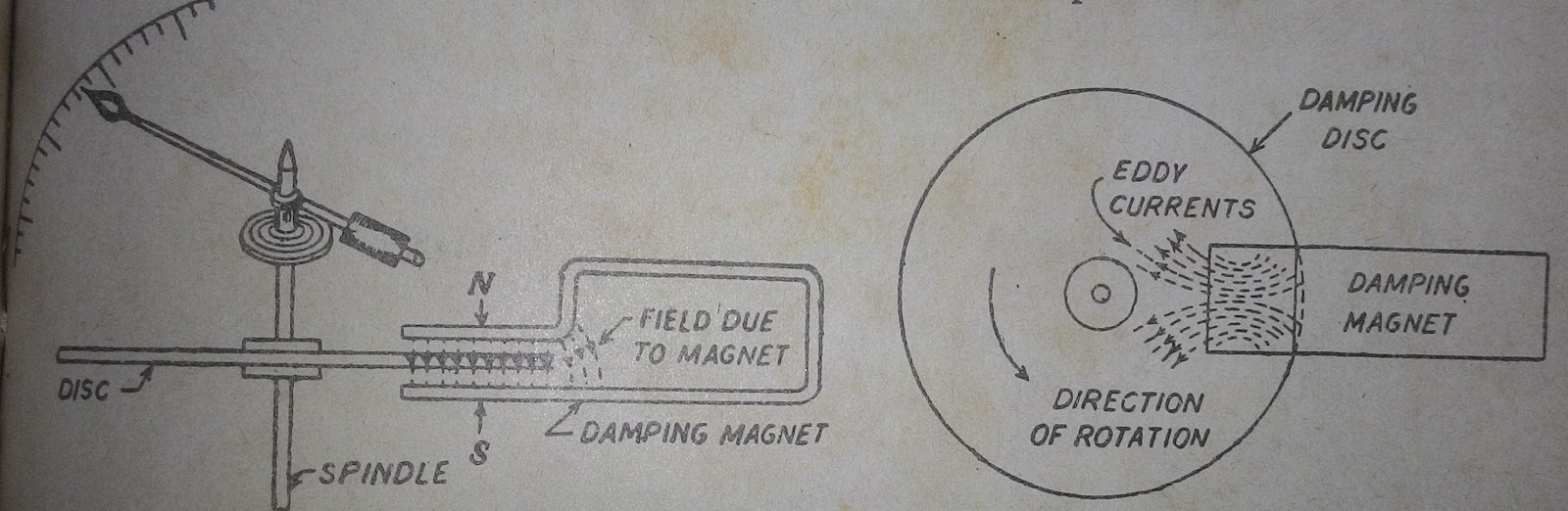
The eddy current form of damping is the most efficient of the three. The two forms of such a damping are shown in fig. It is shown a thin disc of a conducting but non-magnetic material like copper or aluminum mounted on the spindle which carries the moving system and the pointer of the instruments. The disc is so positioned that, its edges when in rotation, cut the magnetic flux between the poles of a permanent magnet. Hence, eddy currents are produced in the disc which flow and so produce a damping force in such a direction as to oppose the very cause producing them. Since the cause producing them is the rotation of the disc, these eddy currents retard the motion of the disc and moving system as a whole.
The figure shows second type of eddy current damping generally employed in permanent magnet moving coil instruments. The coil is wound on a thin light aluminum former in which eddy currents are produced when the coil moves in the field of the permanent magnet. The direction of the induced currents and of the damping force produced by them is shown.
The various types of instruments and the order in which they would be discussed is briefly explained below.
AMMETERS AND VOLTMETERS
Moving Iron Type (both for D.C./A.C.)
The attraction type and,
Repulsion type
Moving Coil Type
Permanent magnet type (for D.C. only)
Electrodynamic or dynamometer (for D.C/A.C.)
Hot wire type (both for D.C./A.C.)
Induction Type (A.C.only)
Split phase type and shaded pole type
Electrostatic type- for voltmeters only (for D.C/A.C.)
WATTMETERS
Dynamometer type (both for D.C./A.C.),
Induction Type (for A.C. Only)
Electrostatic Type (both for D.C. /A.C.)
ENERGY METERS
Electrolytic Type (for D.C.only)
Motor Meters
Mercury Motor Meter: for D.C. work only. Can be used as amp hour or watt hour meter.
Commutator Motor Meter. Used on D.C./A.C. Can be used as Ah.or Wh. Meter.
Induction Type for A.C. only
Clock Meters (as Wh-meters)
MOVING –IRON AMMETERS AND VOLTMETERS
There are two basic forms of these instruments that is the attraction type and the repulsion type. The operation of the attraction type depends on the attraction of a single piece of soft iron into a magnetic field and that of repulsion type depends on the repulsion of two adjacent pieces or iron magnetized by the same magnetic field. For both types of these instruments, the necessary magnetic field is produced by the ampere- turns of a current- carrying coil. In case the instrument is to be used as an ammeter, the coil has comparatively few turns of thick wire so that the ammeter low resistance because it is connected in series with the circuit. In case it is to be used as a voltmeter, then the coil has high impedance so as to draw as small a current as possible since it is connected in parallel with the circuit. As the current through the coil is small, it has large number of turns in order to produce sufficient ampere –turns.
ATTRACTION TYPE
The basic working principle of an attraction- type moving- coil instrument is shown in figure. It is well known that if a piece of an unmagnified soft iron is brought up near either of the two ends of a current carrying coil, it would be attracted into the coil in the same way as it would be attracted by the whole of a bar magnet. Hence, if we pivot an oval shaped disk of soft iron on a spindle between bearings, near h coil the iron disk will swing into the coil when the latter has an electric current passing through it. As the field strength would be strongest at the center of the coil, the oval shaped iron disk is pivoted in such a way that the greatest bulk of an iron moves into the center of the coil. If a pointer is fixed to the spindle carrying the disk, then the passage of current through the coil will cause the pointer to deflect. The amount of deflection produced would be greater when the current producing the magnetic field is greater. Another point worth noting is that whatever the direction of current through the coil, the iron disk would always be magnetized in such a way that it is pulled inwards hence such instruments can be used both for direct as well as for alternating currents. When the current to be measured is passed through the coil or solenoid C, the magnetic field is produced which attracts the eccentrically-mounted disc inwards thereby deflecting the pointer which moves over a calibrated scale.
REPULSION TYPE
It consists of a fixed coil inside which are placed two soft iron rods or bars A and B parallel to one another and along the axis of the coil. One of them i.e. A is fixed and the other B, which is moveable carries a pointer that moves over a calibrated scale. When the current to be measured, is passed through the fixed coil, it sets up its own magnetic field which magnetizes the two rods similarly i.e., the adjacent points on the length of the rods will have the same magnetic polarity. Hence, they repel each other with the result that the pointer is deflected against the controlling torque of a spring or gravity. The force of repulsion is approximately proportional to the square of the current passing through the coil. Moreover, whatever may be the direction of the current through the coil; the two rods will be magnetized similarly and hence will repel each other. In order to achieve uniformity of scale, two tongue shaped strips of iron are used instead of two rods. The fixed iron consists of a tongue shaped sheet iron bent into a cylindrical form; the moving iron also consists of another sheet of iron and is so mounted as to move parallel to the fixed iron and towards its narrower end.
The deflecting torque is due to the repulsive force between the two similarly magnetized iron rods or sheets.
There are two types of possible errors in such instruments, firstly, those which occur both in a.c. and d.c. work and secondly, those which occur in a.c. work alone.
ERRORS WITH BOTH D.C. and A.C.WORK
Error due to hysteresis- because of hysteresis in the iron parts of the moving system, the readings are higher for descending values but lower for ascending values.
The hysteresis error is almost completely eliminated by using Mumetal or Parmalloy which have negligible hysteresis loss.
Error due to stray fields- unless shielded effectively from the effects of stray external fields, it will give wrong readings. Magnetic shielding of the working parts is obtained by using a covering case of cast-iron.
ERRORS WITH ALTERNATING CURRENT WORK ONLY
Changes of frequency produce (i) change in the impedance of the coil and (ii) change in the magnitude of the eddy currents. The increase in impedance of the coil with increase in the frequency of the alternating current is of importance in voltmeters. For frequencies higher than the one used for calibration, the instrument gives lower values. However, this error can be removed by connecting a capacitor of suitable value in parallel with the swamp resistance R of the instrument. It can be shown that the impedance of the whole circuit of the instrument becomes independent of frequency if C=L/R where C is the capacitance of the capacitor.
ADVANTAGES AND DISADVANTAGES
Such instruments are cheap and robust, give a reliable service and can be used both on a.c. and d.c. circuit. Although they cannot be calibrated with a high degree of precision with d.c. on account of the effect of hysteresis in the iron rods or vanes. Hence, they are usually calibrated by comparison with an alternating current standard.
MOVING COIL INSTRUMENTS
There are two types of such instruments i.e. (1) permanent magnet type which can be used for direct current work only and (2) the dynamometer type which can be used for both direct current and alternating current work.
The operation of moving coil permanent magnet type instruments is based upon the principle that when a current carrying conductor is placed in a magnetic field, it is acted upon by a force which tends to move it to one side and out of the field.
As its name indicates, the instruments consists of a permanent magnet and rectangular coil of many turns wound on light aluminum or copper former inside which is an iron core. The powerful U-shaped permanent magnet is made of Alnico and has soft iron pole pieces which are bored out cylindrically. Between the magnetic poles is fixed a soft iron cylinder whose function is,
(I)To make the field radial and uniform and (ii) to decrease the reluctance of the air path between the poles and hence increase the magnetic flux. Surrounding the core is a rectangular coil of many turns wound on a light aluminum frame which is supported by delicate bearings and to which is attached a light pointer. The aluminum frame not only provides support for the coil but also provides damping by eddy currents induced in it. The sides of the coil are free to move in the two air gaps between the poles and core. Control of the coil movement is affected by 2 phosphor-bronze hair springs, one above and one below, which additionally serve the purpose of leading the current in and out of the coil. The two springs are spiraled in opposite directions to neutralize the effects of temperature changes.
When current is passed through the coil, forces act upon it’s both sides which produce a deflecting torque.
Advantages and Disadvantages of moving coil instruments
ADVANTAGES: They have low power consumption and their scales are uniform and can be designed to extend over an arc of 2700 or so. They possess high (torque/weight) ratio. They can be modified with the help of shunts and resistances to cover a wide range of currents and voltages. Further they have no hysteresis loss and they have very effective and efficient eddy current damping. Since the operating fields of such instruments are very strong they are not much affected by stray magnetic fields.
DISADVANTAGES: Due to delicate construction and the necessary accurate machining and assembly of various parts, such instruments are somewhat costlier as compared to moving iron instruments. Some errors are set in due to the aging of control springs and the permanent magnets. Such instruments are mainly used for direct current work alone, but they have been sometimes used in conjunction with rectifiers or thermo-junctions for a.c. measurements over a wide range of frequencies.
Moving coil permanent magnet instruments can be used as ammeters (with the help of a low resistance shunt) or as voltmeters. (With the help of a high series resistance) The principle of moving coil permanent magnet type instruments has been utilized in the construction of the following:
For direct current galvanometers which can be used for detecting extremely small d.c. currents. A galvanometer may be used as an ammeter or as a voltmeter. By eliminating the control springs, the instruments can be used for measuring the quantity of electricity passing through the coil. This method is used for flux meters. If the control springs of such instruments are purposely made of large moment of inertia, then it can be used as ballistic galvanometer.
ELECTRODYNAMIC INSTRUMENTS:
An electrodynamics instrument is a moving coil instrument in which the operating field is produced, not by a permanent magnet but by another fixed coil. These instruments can be used either as an ammeter or as voltmeter but is generally used as a wattmeter. The fixed coils are usually arranged in two equal sections placed together and parallel to each other. The two fixed coils are air cored to avoid hysteresis effects when used on a.c. circuits. This has the effect of making the magnetic field in which moves the moving coil, more uniform. The moving coil is spring controlled and has a pointer attached to it.
The production of the deflecting torque can be understood from above. The current passing through the fixed coil is I1 and that through the moving coil is I2. Since there is no iron, the field strength and so the flux density is proportional to current I1. For more useful information and books on Electrical Engineering please visit for more details ELECTRICAL TECHNOLOGY


0 comments: